Showing posts with label Horizontal Stabilizer. Show all posts

Sunday, March 30, 2014

Empennage Completion... CHECK!

Hi Gang! Over the last two days I've been working to finish the empennage. By finishing the second elevator trim tab today, I've completed all the metal parts of the emp. I still have some fiberglass to do which will probably be done towards the end of building and before paint. I'll have to go back to torque a few things and put torque seal on the nuts. I may have to work with the counterbalance weights to get the balance of the elevators right. They seem fine now but we'll see how they do after all fiberglass work and paint is done.

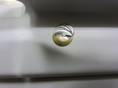
I learned a little tip tonight by experimenting with needing to dimple a hole that was very hard to get to. First, I inserted a block of wood under the hole that needed dimpling. Next, I drilled a #40 hole into the wood. Second, I took the block out and gave it a little camfer to the hole with a deburring tool. Third, I took the block and re-inserted it under the hole, then took the dimple die and inserted it into the hole then hit it a couple good whacks with a ball peen hammer. It's not identical to a normal dimple but it worked pretty well. The reason for this process is that the back side of any of the dies I had, including the pop rivet die, would have interfered with the inner tabs that fold down and damaged one. Below are the pictures showing the steps I used and a couple showing the comparison of both trim tabs. I'm pretty happy with how the second one turned out. I think it's much cleaner. Remember, you can click any of the pictures to enlarge them. :)
Setting Blocks for Drilling/Dimpling
Hole Drilled Into the Block
A Little Countersink with the Deburr Tool
A Couple Whacks with a Hammer and ....
VOILA! A Dimpled Hole
Top is the First Tab, Bottom is the Second.
The Back Side was Actually worse on the First.

I'm now ready to call one of the EAA chapter tech counselors to take a look at my work and give me either a thumbs-up or a list of things to fine tune, fix, clean up or repair. We'll see how that goes and I'll keep you posted on that report.

I recently purchased and received the parts for the RV-7 Service Bulletin 14-01-31. In the empennage, more specifically, the horizontal stabilizer (HS) some builders/owners have shown an area on the that has exhibited cracking. A service bulletin came out warning of the issue and a kit was made by Van's to repair the issue for those that are already flying or currently building. It's about $15 +shipping. For those that are building, this can be used to repair the are of potential cracking they might currently have, which I would guess is doubtful, or they can use it in the future, should any cracks show up. I am going to repair mine before completing my plane as I'd like to have the corrections made before they even have a chance to happen. Right? It makes better sense to repair now so you wouldn't have to disassemble your plane in the future. This will save a lot of time and give me a greater feeling of safety and security. I'll probably save this little project for sometime when I have any lulls in the project. I think it'll make good filler.
Van's RV-7(A) HS Repair Kit
Service Bulletin 14-01-31

Here's a glamour shot of the completion of my empennage and me in the picture to let you know who the builder of this project is.
So Relieved to Have This Kit Finished! Wings Next

That's all for now. Take Care and Thanks For Reading!!
Day Total: 2.6 hrs  HOBBS Meter - 160.9 hrs

Sunday, September 1, 2013

The Elevator that Won't Go Away...

Friday, August 16, 2013
I successfully rolled the leading edge of the right elevator today. It's similar to the rudder and left elevator. I'm pleased. I got all the rod end bearings set to 13/16" and torqued the stop nuts.

The next step was to install the elevators then trim the area of the HS skin where the counterweights need to travel through. Both sides of the HS skin, where the counterweight swings through, extend to a point where they don't allow the swinging action of the elevator to travel. This is inherent in the stamping of the aluminum from Van's. Here are some step-by-step pictures of the process to illustrate more clearly.   
HS Skin Interfering with Counterbalance Arm
Measuring to Clear Material for CB Arm
Material to Bottom Left is to be Removed
Starter Hole for Inside Radius
Hole Enlarged to Final Size for Inside Radius
First Cut. Leave a Little Material so You Can File it
to Where You Want the Edge Exactly
Second Cut & After Cleaning & Rounding Edges
After the Elevator is Installed, This is How It Should Swing
Another Shot Looking Straight Down

This needed to be done in 4 places, top left and right, then bottom left and right. First I needed to measure about 1/8" past the counterweight on the HS skin. Then I extended the line of the outboard edge of the HS skin. Once those two lines were drawn, I needed to set my radius for the inboard and outboard of the cuts. Next, I used snips to cut the excess metal away then file to break the edges and round the inside and outside corners. One down, three to go. Next, I remounted the left elevator to begin the process of setting the elevator "in trail". This means the elevator needs to be a perfect extension of the horizontal stabilizer and at a 0° up and down angle, nothing more. Here, I wanted the counterbalance arm to be even with the HS. I used a simple ratchet clamp to hold it in position. This is where I need the rod end bearings to be exact to the plans so the elevator horn sits exactly where it's supposed to, in conjunction with the opposite elevator and the elevator hinge bearing. If one bearing is not exact to the rest, the horn will sit in or out too far and won't line up properly and I could end up having my controls bind because they aren't in perfect alignment with each other. The measurement of the rod end bearings is 13/16" (7/8" Max). This measurement is from the elevator spar up to the middle of the eye of the rod bearing. Next, I needed to fabricate a bushing which would allow me to drill a hole in the elevator horn through the elevator hinge bearing. A bushing prevents the drill bit from enlarging or marring the hinge bearing. I wasn't able to find anything in my garage so off to Lowes to look for something that would work. I've seen a lot of builders us a drill bushing with a 1/4" outside diameter (OD) and 3/32" inside diameter (ID) purchased from McMaster-Carr. That's okay, if you're not on a budget. That little gem costs a little over $8, not including tax and shipping! I ended up at Home Depot in the specialty hardware drawer section (I couldn't find anything to suit at Lowes). I picked up a 1/4" OD x 3/16" ID aluminum bushing for 95¢, including tax, which will work perfectly. Because the hinge bearing is a hair under 1/4", I needed to turn the aluminum bushing on the ScotchBrite wheel a bit so it would fit. With that accomplished, I was ready to go with drilling.
The Bushing I Purchased From Home Depot
1/4" OD x 3/16" ID
Bushing in Place Ready for Drilling, But Not Yet!

I stopped here as somehow, I either misplaced my AN4-14A bold or I didn't pay attention to my inventory, noting that I received an AN3-14A bolt. This is a note for you future and current builders out there: KNOW YOUR HARDWARE SIZES! Because I was so new to this, I wasn't paying attention to my empennage inventory and making sure the bolt size corresponded with the inventory sheet. Without measuring and as far as I knew, the bolt LOOKED liked an AN4-14A bolt, but alas, it was not. Know the difference between and AN3 and an AN4 bolt. AN3 is 3/16" and  AN4 is 4/16" or 1/4" when you do the math. Needless to say, I need to order a bolt from Van's. No, I won't just order a bolt. That would be WAY too expensive after tax and shipping. I will also order the parts to make another trim tab. YES, I know what I said earlier, "It's just a trim tab people!". Well, I'm a perfectionist too. It looks ugly and I want to replace it. I'll consider this one practice.
Day Total: 3.6 hrs  HOBBS Meter - 148.5 hrs


Saturday, August 17, 2013
Today, I re-measured the rod end bearings to make sure I had everything lined up right. Measure twice (or 50 times), cut once. Right?! I'm waiting until Monday to order my bolt and trim tab parts and receive the order before I start drilling as I want to have the item in hand that needs to fit after drilling.
Day Total: .6 hrs  HOBBS Meter - 149.1 hrs


Monday, August 19, 2013
I placed my order today to Van's for the AN4-14A bolt along with my trim tab replacement parts.


Wednesday, August 21, 2013
I received my Van's order today! =8^)  I plan to get to work and finish the empennage Saturday. I'm anxious to put this behind me and get started on the wings!
Trim Tab Replacement Parts


Tuesday, August 27, 2013
Drilling! So, today I inserted the aluminum bushing into the elevator hinge bearing and went with the #27 drill bit (9/64") to start drilling the left elevator first. It looked like it went well so I took the left elevator off and installed the right one and continued to drill. Next, I used progressively larger bits until 1/4" was achieved. That done, I cleaned the holes then installed both elevators and went to install the AN4-14A bolt. Here's where things go awry. When installing the bolt, I realized that I achieved what many builders before me have accomplished, my holes are too close to the torque tube!
Bolt Shown Too Close to Torque Tube & Bolt Head
Filed Down to Fit in the Area Provided

I tried to do what others had done and that was to grind down one of the facets of the bolt head so it would sit close to the torque tube and still fit straight through the hole. It was very close, but it worked. Next was to see the fitment of the nut to the bolt. NO GO! Dammit! This hole seemed to be way too close. I couldn't even begin to thread the nut onto the bolt. Okay, my mind goes into overdrive here trying to figure out what my options are. I'm seeing dollar signs flying around with replacing the horns and all the work that is entailed with removing rivets... AAGGHHH!! Okay, 1) I can try filling with J-B Weld and try re-drilling. 2) I can get new parts and partially disassemble the elevators. 3) I can take the elevators to a professional welder and have the holes filled, grind them flat and try again. I opted for option 1. So I put a piece of packing tape on the outboard sides of the horns then stood them up vertically. I mixed some J-B Weld and dripped it into the holes. I let that cure overnight.
Hole Filled with J-B Weld. Hope This Works!
Day Total: 1.1 hrs  HOBBS Meter - 150.2 hrs


Wednesday, August 28, 2013
 Okay, the J-B Weld is more than cured by now so I decided to try drilling again. This time I made a jig, of sorts, by taking 2 pieces of angle aluminum and cutting them to about 1½" then marking 7/8" up from the bottom and drilling a 1/4" hole on each. My plan, which I'd read on another builder's site, was to stand the angles on each side of the rod bearing, adjust the rod bearings to 7/8" then trying a bolt through the whole shootin' match to get all the bearings consistent. The angle simulated the hinge brackets on the HS although, they would be standing from the elevator spar instead. 13/16" didn't seem to work well for me previously so I took the 7/8" max. measurement and used that as my mark. After getting all the rod bearings adjusted and set, I commenced drilling, AGAIN!

A note here: I did some research on what other builders have experienced on this task. Some do it the first time successfully and others seem to struggle quite a bit, like I am. Measuring the rod bearings seems to be a chore in some ways. The bearing in the middle rotates around making it difficult to get exactly straight. I did the eyeball method but that didn't seem to work very well for me. Others comment that consistency is difficult to achieve. I realized that 1/2 a turn makes a difference with the rod bearing's height. With that realization, it seems the only way one can make them all consistent is to make sure the direction of the platenuts is the same. How is this achieved you ask? Simple. Hold the platenuts in one hand and the rod bearing in the other with the bearing JUST inserted at the beginning of the screw. Now, turn the bearing in the reverse direction (loosen) until you hear or feel a 'click'. That is where the two starting threads meet or join to thread the two together. Now, make a mark on one end of the platenut and do the same with the rest and put the mark at the same location on all. Make sure to hold the rod bearing the same way with each one, this puts the start of the thread in the same spot every time. Mark the bearing if you need to as well to remember it's position in your hand. Once done, rivet all the platenuts in place with the marks going all the same direction. Now all the rod bearings will be consistent in height and not half a turn off from one another. I didn't do this on the elevators or rudder but plan to on the wings.

So, I set off drilling. I quickly discovered the J-B Weld is good for a great many things, but not as a hole filler to be re-drilled in steel. The bit was actually wandering over to the old hole as the J-B Weld is not as strong as steel. It's epoxy after all. Okay, now I'm extremely frustrated as this emp kit should have been done hours ago. No pictures for this little process. 

I cleaned up the holes by ScotchBrighting them, removing the powder coat around the holes, filing the remainder of the J-B Weld from the inside of the holes and clearing a little powder coat from the ends of the horns to ready them for welding (you need a ground point with the steel). I took my elevators to a local welder to see if they would be able to do them. He said to bring them by Wednesday as he was short-staffed. So, I'm waiting until then to take them.
Hole Cleaned Up & Ready to for a Fill Weld

Another note here: Although I did some welding in my youth in a shop class, I don't possess the skills necessary nor do I have the equipment to try this myself. I've read that TIG welding is better than MIG welding in that TIG has less spatter or spray and it is a cooler weld which is less likely to harden the steel horn which would be more difficult to drill later if it were hardened too much. I'll report the outcome a little later.
Day Total: .6 hrs  HOBBS Meter - 150.8 hrs


Saturday, August 31, 2013
Today, while waiting to take my elevators to be repaired by a professional welder, I decided to do a little work on the fiberglass elevator and rudder tips. Basically, I was just fitting them by marking the excess that needed to be trimmed around the counterbalance weights. So, I inserted them into their places and made marks right a the edge of the CB weight and made notches in both the elevator tips. I did the same for the rudder top tip. I also trimmed the excess of length (depth in this case) of the glass to make it fit into the space provided which will sit at or just above the inside rib line. I still need to trim the elevator tips for depth as well as the HS tips and the rudder bottom cap.
Elevator Tip in Place After Notching
Tip with Notch Cut Out for Clarity

That's it for now. Take Care & Thanks For Reading!
Day Total: 1.2 hrs  HOBBS Meter - 152.0 hrs

Friday, July 6, 2012

Birthday Wishes & First Completion

Happy Belated, 236th Birthday United States! It's been a pretty incredible week with days at work, days off, working on my mistress, etc. I had to work Monday and Tuesday, off Wednesday for our nation's birthday celebration, back to work Thursday and off Friday.

My company has a 9/80 work week. It's confusing as heck at first but pretty nice, and you get used to us pretty quickly. The only nicer work week is the 4/10s. We basically have every other Friday off. We work a full week of 9 hour days, but on the first Friday, the first 4 hours complete the week. The second 4 (only an 8 hour day on working Fridays) are then put towards the next week. That week (the second one) I work Mon-Thurs 9 hour days then off the second Friday. The 4 hours that was carried over from the previous Friday, counts in the second week, completing the 40! Anyway, week was a weird work week, trying to get used to when I needed to go in and when I didn't.

Ok, back to work. Monday saw a little rest from the project and I got back to the plane Tuesday, July 3. This looked like a pretty simple evening. all I had to do was rivet HS-710 and HS-714 reinforcement angles to HS-702, the forward spar. Well, this little chore seemed easier said than done. I struggled a bit on and off with some of the riveting. Everything seemed to be going along hunky dory. I felt good about all the rivets I bucked. Then I turned the spar on its back and BAM!! What the hell are those ugly things?

Ever Put A Smile On A Rivet? I Did!
Frowns In This Case

Yep, I wasn't paying attention to the setting of my rivet gun's rivet set on the rivets here and I think that when I did the initial buck, I put the gun down and checked the shop head with the guage tool and felt it (they) needed a little more and when I picked up the gun, it felt like I had the tool on the head. WRONG! Time to drill out some rivets. Here's the process. Be sure to LOOK and make sure the rivet gun is ON and read to go. Hope this helps other builders:
1) Secure Your Work Piece
2) Mark Your Rivet with a Marker
Then Use a Center Punch
3) Drill the Rivet on Center to the Bottom of
the Rivet Head

4) Insert a Punch Sized to the Hole
#30 In This Case
5) Snap the Head of the Rivet Off
This Exposes the Hole & the Rest of the Rivet
6) Use a Light Hammer to Punch out the Rivet
If Done Right, You'll Have a Clean Hole to Re-Rivet
Interestingly enough, I boogered the same locations, opposite of each other. I managed to buck the replacements without incident.

The next SIMPLE part of this little task was to rivet the nose and main HS-404 and HS-405 ribs. Well, hold on. Not so fast! I am starting to liken this riveting thing to my golf game. I love to play golf. I do not profess to be the greatest player. I'm the kind of golfer who knows how to play the game well enough to love to hate the game. I've never taken a lesson, save a tip or two on the practice range with the course pro walking up and down helping golfers here and there. Like drugs, the first one is free, then you're hooked to pay for the rest. Bad analogy, but it fits. That said, I play out of hazards (sand traps, the rough, out of the trees, out of the woods, etc.) quite often. Well, I've become pretty adept at getting out of hazards over the years. Riveting is, for me, a very similar process right now. Though I've had lessons in riveting, I'm no professional. I get by, for now. I check my shop heads often for height and shape to make sure they're straight and the right height. And yes, occasionally I have to "get out of a hazard" and drill one out. Like my hazard game, I'm becoming very adept at drilling out a rivet without damage to the hole, i.e., enlarging, elongating, etc. I know that in time, I'll become more adept at riveting and hopefully, forgo the need for drilling out rivets regularly. So, with that, it took me 2 hours to rivet the two reinforcement angles and the 4 ribs to the forward spar. I drilled several (I lost count) rivets out and re-riveted the same ribs a few times. Part were because I didn't set them very well to begin with and part were because I didn't follow the plans and directions carefully. At one point, I installed the HS-404 ribs without the HS-405 attached with them. They are supposed to be riveted TOGETHER! The thing that confused me was the -404 ribs only use 2 rivets for attachemnt and the -405 ribs use 4. Even with that, I was thinking in a line of 4 rivets, the front rib used the inner two rivet holes and the aft, -405 rib used the outer two. WRONG! Well, I finally got them set to satisfaction, nice and clean!
HOBBS Meter - 37.3 hrs

Wednesday, July 4, American Independence Day! - Today, I started finishing up the horizontal spar (HS) by assembling the forward spar assembly to the HS-601PP skins. This is COOL! It's finally starting to look like part of an airplane. First, I riveted the HS-707 nose rib to the top of the left skin. This is easier said than done. After dimpling the skins and the ribs, the Cleko (cleco) fasteners don't stay in the holes very well. Typically, you can get by with fastening every other hole, but in this case, I need a cleco in every hole. In addition, I needed to be a little creative with that little chore. I used a little duct tape to hold the aft part of the skin trailing edges together, along with another trick. This seemed to work pretty well. I was able to get the rib tight against the upper skin for riveting. Only one drill-out here.
A Little Trick to Get the Skin Tight
Against the HS-707 Nose Rib. No Duct Tape Here


Next, I cleco'd the end, HS-706 rib to the skin then HS-708 temporarily to the skin and the aft flange of that -708 nose rib. This helps hold that rib in place for the riveting the bottom part of the rib to the skin.
HS-707 Nose Rib Riveted to Top of Skin
Getting Ready to Rivet Bottom


After that, remove the -708 rib. Cleco the -706 end rib and -707 nose rib to the skin then cleco -708 back on, then blind rivet. You can't get to the front of this area to hold a bucking bar so you have to put 3 blind rivets in. No bad jokes here about 3 blind mice, I'm punchy enough at this point! :o)  Next, I riveted that -706 end rib to the -702 forward spar. I then riveted the skin to the rest of the ribs. Now, REPEAT all that you just did for the right side skin. Well, it's 9:00 pm and time to watch fireworks so I'll finish the bottom of the right skin riveting to the ribs and spar. I'll pick up here tomorrow.
Ready to Finish Bottom Riveting
HOBBS Meter - 42.9

Thursday, July 5 - I finished the right side bottom of the skin to the ribs and spar. Next, I attached the rear spar assembly to the HS-404, -405, -706 and -601PP skin. There are blind rivets to set on the HS-708 rear spar but you'll do this last, per the directions. I had some more dirll-outs but not many. I had to drill a rivet out that created a figure 8 hole. So, I cut a couple pieces of scrap aluminum and put them on on either side of the damaged spar hole, drilled the new pieces and shaped them to make sure they'd fit the area comortably. I then bucked a new rivet here with the next sized rivet to compensate for the newly added, reinforcement aluminum. Worked like a charm.
Figure 8 Hole Before the fix
The Back Side with Reinforcement

I riveted the skin to the end ribs, HS-706, and inboard ribs, HS-404 and -405. Be careful here, there are 10 rivets that you DO NOT SET. You'll set these later for the faring that will go on the TOP side of the HS. Read the plans and you'll see them. I finished by riveting the skin to the rear spar assembly then pulling the blind rivets (same as a pop rivet) on the HS-708 rib. With that, "Congratulations! You've finished the first major sub-assembly on your new airpane".
Horizontal Stab Complete!

After I turned the HS over, I found an empty rivet hole right smack dab in the middle of the left, bottom skin! AARRGGHHHH! I'll either put a pop rivet (not very likely) there or try to be creative and maybe tape a bucking bar to the end of half a yard stick and slide that in a lightening hole (makes the piece lighter, not like a bolt of lightening, silly) then try to buck it that way. We'll see. Remember the reference of "playing out of hazards" earlier? Well, I think this will be a new trick I can add to my bag of tricks, if I can pull it off. I'll let you know how that goes. Until then, Take Care and Thanks for Reading!
HOBBS Meter - 46.5

Monday, July 2, 2012

First Full Day

Huge day today. This was my first, full project day of over 8 hours. It felt really good to get as much accomplished as I did today. I finished dimpling the horizontal stabilizer (HS) skins. I realized when I finished that I forgot a step in the directions! ARGH!! I hate when that happens! I deburred all the holes in the ribs and spars but forgot to hit the holes in the HS skins. Well, I checked them all and they felt/looked pretty good to me. There were a few that I hit with a debur tool to smooth 'em out. I smoothed all the other parts and even took them across the ScotchBrite (SB) wheel. I even found what appeared to be a little scuff/gouge on the edge of one of the skins. I took it to the SB wheel to remove the offending booger. It turned out ok. This won't be seen later as it is located next to the fuselage and will be covered with a cowling.
Cleanup on a Little Gouge on the HS Skin
The next step is cleaning all the surfaces for priming. I'm using acetone for the cleaning process. I can't seem to locate MEK (methyl ethyl ketone) at any of the DIY stores. Granted, I only checked the big two. It's a good solvent and even used as a plastics adhesive. I think businesses are replacing some solvents with other, safer products. I thought of using denatured alcohol but acetone works pretty well. I'm using gloves to protect my hands (don't want anyone commenting on the safety issues here). I should be using a respirator as well. I'll start using one. So, I got all the parts cleaned and re-marked where the acetone cleaned off the original, part markings. You'll need to make sure you do this so you don't go bonkers with mis-matched holes! You'll also want to make sure that if you can't remember the orientation of the part, take notes. Something like this: on a piece of paper, draw the orientation of the part, something obvious to you so you can't goof it up, e.g., up, down, forward, aft, inboard, or outboard and whether it is to be used on the left or right side. Then, clean the part everwhere the primer is to protect it. Now take your blue Sharpie (recommended by many as they seem to last longer) and mark the part again if you happened to clean the original markings off. I'm basically hanging all my parts from a wire and giving one light coat of primer then after 5-10 minutes, spraying a second heavier coat making sure to cover any exposed aluminum. I read the spray can initially but took particular notice the second time around of the notation about using 320 grit abrasive. This is supposed to prepare the area for better adhesion of the primer. I didn't do this step. I hope I'm ok with the way I've been priming. Of course, if you do this, the steps areas follows: 1) Shake can for 1 minute 2) use SEM solvent to clean the part 3) use 320 grit sandpaper 4) use SEM solvent to clean the part 5) spray 1-3 light coats 6-8" away from the part. That's a lot of steps and time. I'll give the fingernail scratch test to the parts I've primed later to see how they hold up. This primer, SEM, dries pretty quickly. The can says 15 minutes but I've been noticing the parts are drying sooner than that and seem to have a pretty tough coating.
Parts  Clean and Hung, Ready for Primer
Parts Primed with a Couples Coats. Looking Good!
I had forgotten to clean and prime a couple parts as I was ready to start assembling and realized that they were missing from the assembly batch. OOPS! So, I pulled them out, cleaned then primed them and waited for them to dry then I started to assemble them. That little missed step added an extra hour to the process.
Priming the Inside of the HS Skins
Inside Shot of the HS Skin
So, first you tape over a few of the rivet holes as you don't want to inadvertently rivet them without the parts being in place first. Otherwise, you'll be cussing yourself later. These holes are for the hinge brackets and ribs. First you'll rivet the HS-603PP rear spar and HS-609PP spar support bars together. Using the pneumatic rivet squeezer for this process is SO nice! It takes a few rivets to get the setting right on the squeezer for the perfectly set rivet. Next, rivet the HS-412 & -413 hinge brackets to the spar. The directions have me using an AN470AD4-5 rivet for the outboard hinge brackets. I set the first one and it was way too long in my opinion. I went down to a 4-4 and this seemed to be the ticket! so, I had to drill out a total of only 2 rivets. Not bad. I know, with a pneumatic squeezer, you shouldn't have this problem. Well, setting that 4-5 rivet leaned the shop head over (bent it). So, rivet drill-out #1. Then I found where a manufactured head didn't quite set flat. So, rivet drill-out #2. The rest went pretty smoothly. FYI - for the layperson, here's the 411 on a manufactured head and a shop head of a rivet. The manufactured head is the end of the rivet that has a head on it coming from the manufacturer (only one end of the rivet has a head on it before it's set. The shop head is what you end up with after you set a rivet, the mushroomed, flat head on the other end of the rivet when you're done setting it.

Lastly, I bolted the center hinge bearing assembly and torqued the bolts to between 20 and 25 in. lbs. Next is to start on the foward spar assembly.
Our Shop Worker In Process of Riveting
Half Riveted - Tape is NON-Rivet Holes (For Now)
Nice, Pretty Line of Rivets
Rear Spar Completed With Hinge Brackets
That's it for today my peeps. I'm pooped. Hmm, too pooped to peep! I'm getting punchy. Take Care and Thanks for Reading!
HOBBS Meter - 35.3 hrs

Sunday, July 1, 2012

Dimples, Dimples, Dimples

Today, I began the "drill, debur, dimple, repeat" process. There will be a LOT of this throughout the project. I have actually already started the drilling process. I've merely added the lovely and exciting steps of deburring and dimpling and repeating these processes. Basically, I already match-drilled all the spars and ribs to the HS skins. Today I used deburring tools to clean some of the more rough edges of the parts, which I'll put on the ScotchBrite wheel later to give them an even cleaner edge. A ScotchBright wheel is not a grinding stone on the grinder but a softer abrasive wheel. It's like a compacted scrubby shaped like a 6"x1" wheel and attached to a grinder. It does a heckuva job cleaning, polishing and getting rid of rough edges of the manufactured pieces. It's called a Cut & Polish wheel but some builders have given it a more appropriate name, Cut & Bleed wheel. It'll do a number on ya if you're not paying attention. So far (* * * knock on wood), I'm fortunate. I deburred and dimpled the spars and ribs this morning for about an hour.
This is One of the Spars Which has Been Dimpled
Left and Right HS Parts: Ribs, Spars and
Reinforcement Angles
The next task, which has nothing to do with the plane, was to make a jig to install around the DRDT-2 Dimpler. Ok, it DOES have something to do with the plane but not so literally. The mfr gives you plans to build a platform around the dimpler to help support the larger pieces of aluminum, making it easier to dimple the larger sheets. I spent a few hours on fabricating the platform (jig) then had to run to the DIY store for some carpet to put on the bugger. I think it turned out pretty well.
This is One of the Sides of the Jig for the
DRDT-2 Dimpler
Bottom of the One Side Showing the Support Leg
Completed & Installed with Carpet
Then I went in to watch a movie (We Bought A Zoo) with my wifey for a couple hours then back out to the mistress. I've not given her a name yet, so far, just the mistress. Speaking of names, I've been thinking of my tail number for quite some time and have basically narrowed it down to one. It's available right now in the FAA database. I'm just not completely sold on it and want to give it a little more thought. Right now, I'm thinking N763PW (seven six three pappa whiskey). It has a ring to it and the pappa whiskey seems to flow well. It's my birth month and year and my initials. Like I said, I'm not completely sold. My Van's builder number (which is also the serial number for my mistress) is 74092 and doesn't really have anything catchy that I like. I've thought of other things in combination with my wife such as our names, our anniversary, etc., but haven't really come up with but a few ideas that just aren't on the top of the list. So, I'll keep giving it thought. It's much like a vanity plate on your car. It only costs $10 to reserve it through the FAA and about $10 a year to keep it reserved until it's officially yours. The cool thing is once it is given to you, you don't have to pay for it every year like your car tag. Here in California, you pay for the vanity plate every year. It's a recurring cost added to your registration fee.

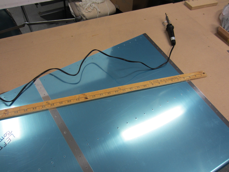
After the movie, I went out to the ACME garage (Aircraft Construction & Manufacturing Enterprise) for a couple more hours to work on putting the carpet on the jig then I went back to the stabilizer skins. I removed the inside blue plastic on the skins and used a soldering iron to make strips around the skin holes to remove the platic just around the holes. You don't want to remove all the platic because you want to leave as much on as possible to procect the alclad surface from scratches. However, you want to remove the plastic around the holes before dimpling so the plastic doesn't affect the dimpling itself. So, I removed the necessary blue plastic from both HS skins and started dimpling one of the skins. I completed about 1/3 of the dimpling on the first skin. I'll pick up there tomorrow.
Blue Plastic Strips Removed From Around
Skin Drill Holes

The Soldering Iron & Yardstick Used to
Remove the Blue Plastic Around the Skin Holes

That's it for this evening my peeps. Take Care and Thanks for Reading!
HOBBS Meter - 29.3